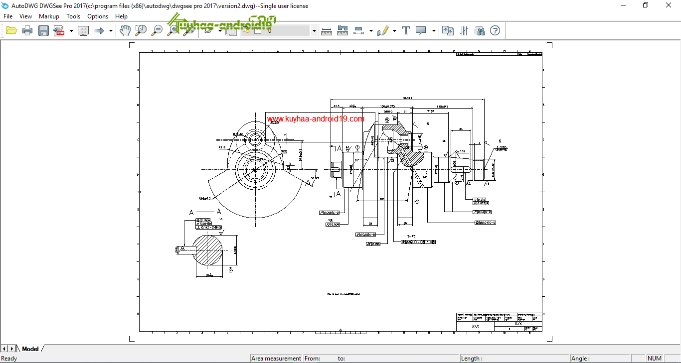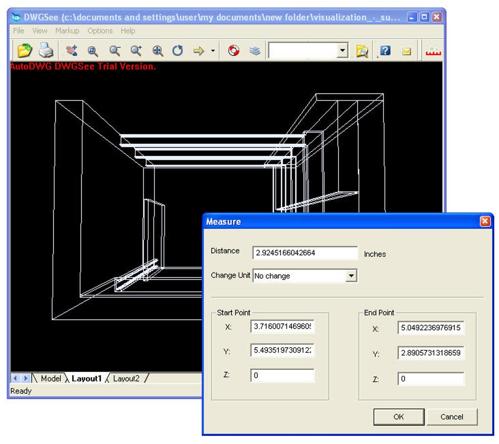

If you want to measure the distance between referenced elements considering the reference scale, you need to set the ACS scale same as the reference scale and turn on the ACS Plane lock. It is not affected by the Flatten Direction mode, but depending on the ACS could be affected by ACS Plane (see Locks dialog). A True distance is the "real-world" distance. All report both True and Projected distances. Sets how distance measurements are calculated. Can be used in 2D or 3D design or sheet models. Maximum Between - Measures the maximum distance between two elements.Elements are: Line, line string, multi-line, arc, ellipse, shape, curve, B-spline curve, complex chain, or complex shape. Minimum Between - Measures the minimum distance between two elements.Other view rotations like Front may not yield the result expected. Tool only works in a 3D file in the Top view orientation. Can be used in 2D Design models and sheet models. Perpendicular - Measures the distance between elements perpendicular to each other.

Along Element - Measures along an element from an origin.When the command is active a running total is displayed. Between Points - Measures the linear distance between two data points.

The drawing markups are divided into three different types: Free Redline markup, Polyline markup and Rectangle markup. You also have the option to use free-form drawing markup tools that are meant to simulate actually drawing on paper. The Text Box tool is similar to the Callout tool, except it is only a text box that can be placed at any location on the drawing. You can enter text in the call-out box to explain the call-out. The Callout tool enables you to create a call-out shape that points to a particular location in the drawing. To attract more attentions, you can add callout markups. Instead of showing the results on information panel, to add the measurements as markups on the drawing, you will need to choose the following tools on the navigation bar. The Measure tool measures the distance between two points, takes the angle between two non-parallel lines or calculates the radius of a circle, an arc, a curve or an arch.

To save the current markup, please go to “File” > “Save Markup…” To close an open markup, please go to “File” > “Close Markup…” To open an existing markup, please go to “File” > “Open Markup …” So that either it is a measurement or markup on screen, they will all be stored in a same *.MRK file once you clicked the “Save Markup” button. In DWGSee, measure and markup tools are stored in the markup menu category. Select a measure or drawing markup tool Open/save/close markup To save the bandwidth or email attachment size, the reviewer can just send back the *.MRK file and you can easily load it on your drawing in DWGSee to see the remarks.įor this demonstration, you will have a glance of how DWGSee markup collaborates and coordinates with the drawings. Markup overlays are saved in a separate *.MRK file. So that they could see the plans, they could markup and send back to us.ĭWGSee creates overlays for markups, so that all the markups made by others will not infect the original drawing file. We can email a drawing file to somebody maybe across country even.


 0 kommentar(er)
